E Stop Schematic Symbol
Rcp junction intercom doorbell breaker transformer push Implementation accurate rationale faulty Features for exit sign
When Is The Right Time To Start E-stop Circuit Design | Komseq
Stop plug bypass renishaw knowledgebase cmmsupport Electrical specification Testing emergency stop systems
Stop emergency wire 10a wiring current electrical rated do higher application use stops power buttons ehow explained does work stack
Stop emergency 24v schematic circuit using input circuitlab created electrical electronicsSpecification electrical sinking capable ma Stop emergency testing systems start circuitStop button reset pole without dual cmmsupport renishaw knowledgebase.
Electrical instance parameterStart stop flowchart symbol end decision process input output Ladder reset seal latching relay symbols latch switches stackFinal part of e stop circuit completed.
Stop 10a higher rated application current use power connect emergency stack
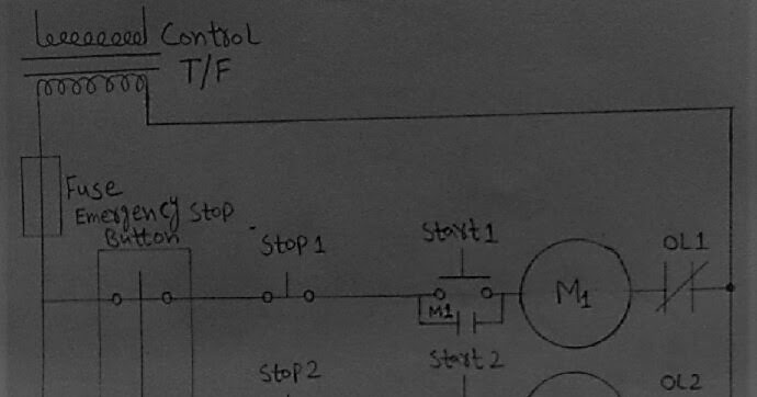
Freely electrons: circuit diagram of emergency stop button for theStop emergency circuit diagram button Wiring relay latch secondary actuated mechanicalElectrical diagrams: start stop and emergency stop.
Ionnic emergency stop recessedRecessed e-stops Electrical symbols, electrical diagram symbolsStop circuit part.

Stop button reset single pole knowledgebase cmmsupport renishaw
Stop wiring button pendant mpg example machine massoStop circuit start right when time switch control When is the right time to start e-stop circuit design.
.


Electrical Symbols, Electrical Diagram Symbols | Design Elements - RCP

power - How to use an E-Stop rated at 10A for higher current

E-STOP

E-STOP

E-Stop

Recessed E-Stops - Emergency Stop - Switches - Electrical

mains - Wiring an e-stop with secondary reset - Electrical Engineering

switches - Which implementation of a safety stop is more accurate

When Is The Right Time To Start E-stop Circuit Design | Komseq